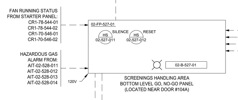
This electrical diagram details the connections for the screenings handling area bottom level go, no-go panel, located near door number 104A with tag 02-B-527-01 and fed by 120V power. Input signals include fan running status from the starter panel for circuits CR1-78-544-01, CR1-78-544-02, CR1-70-546-01, and CR1-70-546-02. Hazardous gas alarm inputs are connected from transmitters AIT-02-528-011 through AIT-02-528-014. The panel includes silence switch HS 02-527-011 and reset switch HS 02-527-012.
Members view this detail in full resolution, download the CAD files (SVG, PDF), and can adapt it in the built-in CAD editor — export DXF, DWG, or PDF.
Start membership