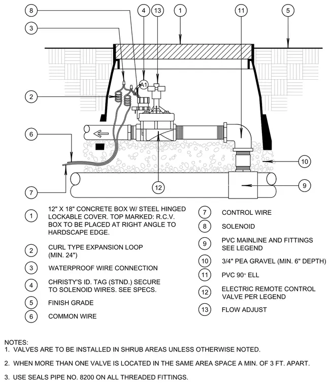
An electric remote control valve is housed inside a twelve by eighteen inch concrete box featuring a steel hinged lockable cover marked R.C.V., set flush with the finish grade and positioned at a right angle to the hardscape edge. The assembly connects to a polyvinyl chloride mainline and fittings resting on a minimum six-inch depth of three-quarter-inch pea gravel bed, incorporating a polyvinyl chloride ninety-degree elbow and a flow adjust valve. Waterproof wire connections and a Christy's standard identification tag secure to the solenoid wires alongside a curl-type expansion loop with a minimum twenty-four-inch length. Control and common wires route into the enclosure, while thread sealant number 8200 applies to all threaded fittings. Valves install in shrub areas unless noted otherwise, maintaining a minimum three-foot spacing when multiple units share the same location.
1 2 4 3 5 6 9 11 10 8 8 13 12 12 13 7 7 9 10 5 11 1 4 3 2 6 NOTES: 1. 2. 3. A1 12" X 18" CONCRETE BOX W/ STEEL HINGED LOCKABLE COVER. TOP MARKED: R.C.V. BOX TO BE PLACED AT RIGHT ANGLE TO HARDSCAPE EDGE. CURL TYPE EXPANSION LOOP (MIN. 24") WATERPROOF WIRE CONNECTION CHRISTY'S ID. TAG (STND.) SECURE TO SOLENOID WIRES. SEE SPECS. FINISH GRADE CONTROL WIRE SOLENOID PVC MAINLINE AND FITTINGS SEE LEGEND 3/4" PEA GRAVEL (MIN. 6" DEPTH) PVC 90 ELL ELECTRIC REMOTE CONTROL VALVE PER LEGEND FLOW ADJUST VALVES ARE TO BE INSTALLED IN SHRUB AREAS UNLESS OTHERWISE NOTED. WHEN MORE THAN ONE VALVE IS LOCATED IN THE SAME AREA SPACE A MIN. OF 3 FT. APART. USE SEALS PIPE NO. 8200 ON ALL THREADED FITTINGS. COMMON WIRE
Members view this detail in full resolution, download the CAD files (SVG, PDF), and can adapt it in the built-in CAD editor — export DXF, DWG, or PDF.
Start membership