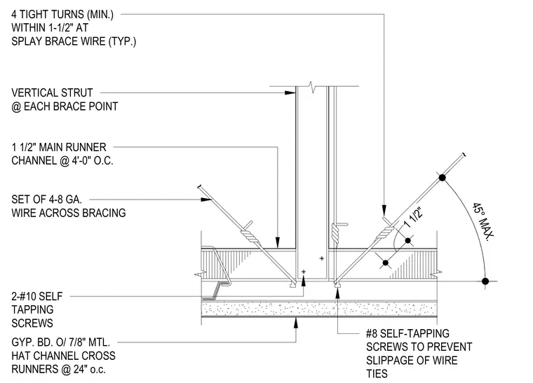
A vertical compression strut extends upward from a suspended ceiling grid, stabilized by splay brace wires set at a maximum angle of forty-five degrees. The ceiling framing consists of one-and-a-half-inch main runner channels spaced at four feet on center, supporting seven-eighths-inch metal hat channel cross runners at twenty-four inches on center, finished with gypsum board. Splay brace wires feature a set of four eight-gauge wires across the bracing, secured with four tight turns minimum within one-and-a-half inches and number eight self-tapping screws to prevent slippage of the wire ties. A vertical strut is positioned at each brace point and connected using two number ten self-tapping screws.
4 TIGHT TURNS (MIN.) WITHIN 1-1/2" AT SPLAY BRACE WIRE (TYP.) VERTICAL STRUT @ EACH BRACE POINT SET OF 4-8 GA. WIRE ACROSS BRACING #8 SELF-TAPPING SCREWS TO PREVENT SLIPPAGE OF WIRE TIES 1 1/2" MAIN RUNNER CHANNEL @ 4'-0" O.C. GYP. BD. O/ 7/8" MTL. HAT CHANNEL CROSS RUNNERS @ 24" o.c. 2-#10 SELF TAPPING SCREWS 45° MAX. 1 1/2" ~ ~
Members view this detail in full resolution, download the CAD files (SVG, PDF), and can adapt it in the built-in CAD editor — export DXF, DWG, or PDF.
Start membership