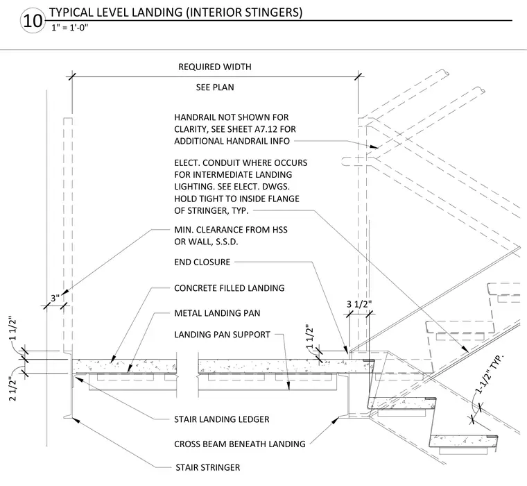
A typical level landing constructed with a two-and-a-half-inch concrete-filled metal landing pan supported by a stair landing ledger and cross beam beneath the landing. The assembly frames into steel stair stringers, maintaining a minimum clearance of one and one-half inches to three inches from hollow structural section columns or adjacent walls. Electrical conduit is coordinated where required for intermediate landing lighting. Handrail components are omitted for clarity and referenced to separate architectural sheets.
2 1/2" CONCRETE FILLED LANDING END CLOSURE METAL LANDING PAN LANDING PAN SUPPORT STAIR LANDING LEDGER CROSS BEAM BENEATH LANDING STAIR STRINGER SEE PLAN REQUIRED WIDTH ELECT. CONDUIT WHERE OCCURS FOR INTERMEDIATE LANDING LIGHTING. SEE ELECT. DWGS. HOLD TIGHT TO INSIDE FLANGE OF STRINGER, TYP. 1 1/2" 3 1/2" MIN. CLEARANCE FROM HSS OR WALL, S.S.D. 1-1/2" TYP. 1 1/2" 3" HANDRAIL NOT SHOWN FOR CLARITY, SEE SHEET A7.12 FOR ADDITIONAL HANDRAIL INFO 1" = 1'-0" 10 TYPICAL LEVEL LANDING (INTERIOR STINGERS)
Members view this detail in full resolution, download the CAD files (SVG, PDF), and can adapt it in the built-in CAD editor — export DXF, DWG, or PDF.
Start membership