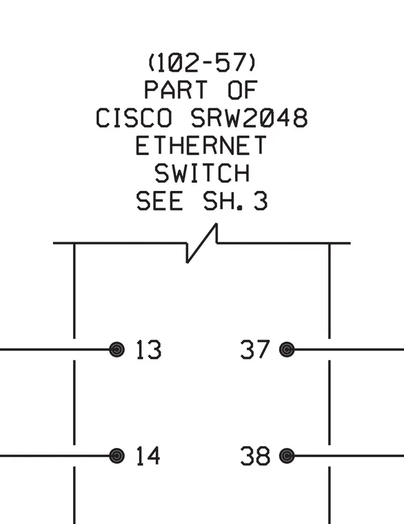
The diagram displays a schematic representation of a Cisco SRW2048 Ethernet switch part numbered 102-57, referencing sheet three for further details. Numbered terminal points thirteen, fourteen, thirty-seven, and thirty-eight connect to the switch module via designated line leads. The layout outlines the communication hardware node connections within the electrical and telecommunication infrastructure.
Members view this detail in full resolution, download the CAD files (SVG, PDF), and can adapt it in the built-in CAD editor — export DXF, DWG, or PDF.
Sign in to subscribe