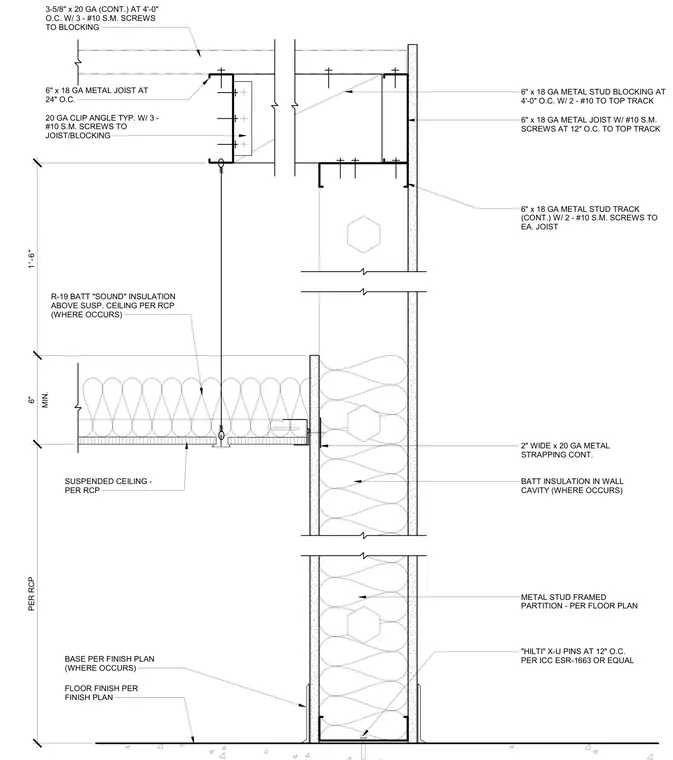
This interior partition detail shows a cold-formed steel stud wall framing running parallel to overhead metal floor or ceiling joists. The wall uses 6-inch by 18-gauge continuous tracks secured to the floor slab with Hilti X-U pins spaced at 12 inches on center. The stud cavity accommodates batt insulation and 2-inch wide by 20-gauge continuous metal strapping where specified. Overhead, 6-inch by 18-gauge metal joists spaced at 24 inches on center connect via 20-gauge clip angles secured with three number 10 sheet metal screws to each joist and blocking member. A suspended ceiling integrates with the partition, backed by R-19 sound attenuation batts installed above the ceiling plane where indicated.
SUSPENDED CEILING - PER RCP METAL STUD FRAMED PARTITION - PER FLOOR PLAN BATT INSULATION IN WALL CAVITY (WHERE OCCURS) 2" WIDE x 20 GA METAL STRAPPING CONT. R-19 BATT "SOUND" INSULATION ABOVE SUSP. CEILING PER RCP (WHERE OCCURS) 1'-6" MIN. 6" PER RCP BASE PER FINISH PLAN (WHERE OCCURS) FLOOR FINISH PER FINISH PLAN 6" x 18 GA METAL JOIST W/ #10 S.M. SCREWS AT 12" O.C. TO TOP TRACK 6" x 18 GA METAL STUD BLOCKING AT 4'-0" O.C. W/ 2 - #10 TO TOP TRACK 3-5/8" x 20 GA (CONT.) AT 4'-0" O.C. W/ 3 - #10 S.M. SCREWS TO BLOCKING "HILTI" X-U PINS AT 12" O.C. PER ICC ESR-1663 OR EQUAL 6" x 18 GA METAL STUD TRACK (CONT.) W/ 2 - #10 S.M. SCREWS TO EA. JOIST 6" x 18 GA METAL JOIST AT 24" O.C. 20 GA CLIP ANGLE TYP. W/ 3 - #10 S.M. SCREWS TO JOIST/BLOCKING
Members view this detail in full resolution, download the CAD files (SVG, PDF), and can adapt it in the built-in CAD editor — export DXF, DWG, or PDF.
Start membership