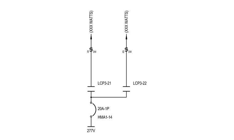
An electrical schematic details a 277V lighting control circuit powered through a twenty-amp single-pole switch designated as HMA1-14. The circuit feeds two separate lighting control points, LCP3-21 and LCP3-22, each terminating at dimming-capable fixtures rated for XXX watts. The wiring diagram shows the switch leg connections, circuit designations, and voltage supply for architectural lighting control integration.
Members view this detail in full resolution, download the CAD files (SVG, PDF), and can adapt it in the built-in CAD editor — export DXF, DWG, or PDF.
Start membership