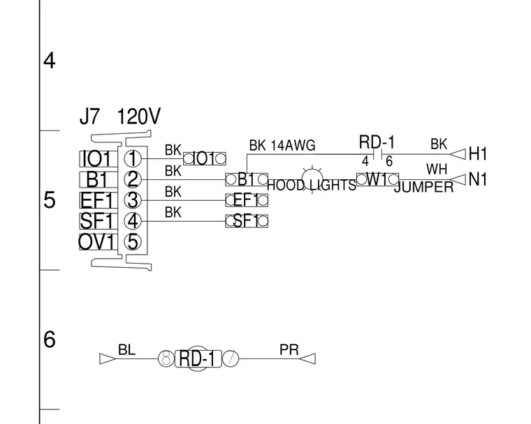
An electrical schematic shows connector J7 wired with 14 AWG black and white conductors supplying 120 volts to hood lights. Terminal connections include IO1, B1, EF1, SF1, and OV1 interfacing with numbered pins one through five. Jumpers and wire markers RD-1, H1, and N1 maintain continuity across the circuit.
PR BL N1 H1 5 OV1 4 SF1 3 EF1 2 B1 1 IO1 120V J7 BK BK BK BK BK 14AWG BK 6 4 RD-1 8 7 RD-1 HOOD LIGHTS WH B1 EF1 SF1 IO1 JUMPER W1 4 5 6
Members view this detail in full resolution, download the CAD files (SVG, PDF), and can adapt it in the built-in CAD editor — export DXF, DWG, or PDF.
Start membership