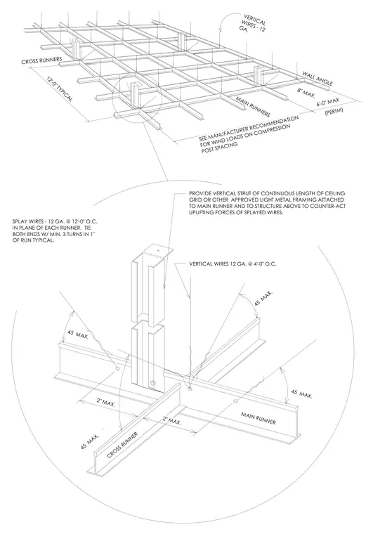
The suspended ceiling grid consists of main runners spaced twelve feet typical and cross runners tied with twelve-gauge vertical wires spaced at four feet on center, and perimeter wires at six feet maximum. Twelve-gauge splayed wires are placed at twelve feet on center in the plane of each runner and tied at both ends with a minimum of three turns in one inch of run. A vertical strut of continuous light metal framing acts as a compression post, attached to the main runner and the structure above to counteract uplifting forces from the splayed wires. Manufacturer recommendations govern wind loads for compression post spacing.
CROSS RUNNERS 12'-0" TYPICAL MAIN RUNNERS SEE MANUFACTURER RECOMMENDATION FOR WIND LOADS ON COMPRESSION POST SPACING VERTICAL WIRES - 12 GA. 6'-0" MAX (PERIM) WALL ANGLE 8" MAX. 45 MAX. 2" MAX. CROSS RUNNER 2" MAX. 45 MAX. MAIN RUNNER 45 MAX. 45 MAX. SPLAY WIRES - 12 GA. @ 12'-0" O.C. IN PLANE OF EACH RUNNER. TIE BOTH ENDS W/ MIN. 3 TURNS IN 1" OF RUN TYPICAL. PROVIDE VERTICAL STRUT OF CONTINUOUS LENGTH OF CEILING GRID OR OTHER APPROVED LIGHT METAL FRAMING ATTACHED TO MAIN RUNNER AND TO STRUCTURE ABOVE TO COUNTER-ACT UPLIFTING FORCES OF SPLAYED WIRES. VERTICAL WIRES 12 GA. @ 4'-0" O.C.
Members view this detail in full resolution, download the CAD files (SVG, PDF), and can adapt it in the built-in CAD editor — export DXF, DWG, or PDF.
Start membership