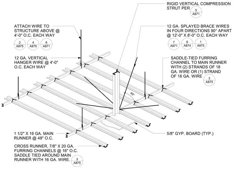
A suspended gypsum ceiling support and bracing grid comprises twelve-gauge vertical hanger wires attached to the structure above at four feet on center each way. One-and-a-half-inch by sixteen-gauge main runners are spaced at forty-eight inches on center, supplemented by rigid vertical compression struts. Seven-eighths-inch by twenty-gauge cross runner furring channels are spaced at sixteen inches on center and saddle-tied around the main runners using sixteen-gauge wire or two strands of eighteen-gauge wire. Twelve-gauge splayed brace wires extend in four directions ninety degrees apart at twelve feet by eight feet on center each way. Five-eighths-inch gypsum board finishes the ceiling assembly.
A874 6 A875 4 A871 6 A871 5 A871 7 A875 2 A875 3 A875 3 ATTACH WIRE TO STRUCTURE ABOVE @ 4'-0" O.C. EACH WAY 12 GA. VERTICAL HANGER WIRE @ 4'-0" O.C. EACH WAY RIGID VERTICAL COMPRESSION STRUT PER 1 1/2" X 16 GA. MAIN RUNNER @ 48" O.C. 12 GA. SPLAYED BRACE WIRES IN FOUR DIRECTIONS 90° APART @ 12'-0" X 8'-0" O.C. EACH WAY SADDLE-TIED FURRING CHANNEL TO MAIN RUNNER WITH (2) STRANDS OF 18 GA. WIRE OR (1) STRAND OF 16 GA. WIRE 5/8" GYP. BOARD (TYP.) CROSS RUNNER, 7/8" X 20 GA. FURRING CHANNELS @ 16" O.C. SADDLE TIED AROUND MAIN RUNNER WITH 16 GA. WIRE. A875 1 45°
Members view this detail in full resolution, download the CAD files (SVG, PDF), and can adapt it in the built-in CAD editor — export DXF, DWG, or PDF.
Start membership