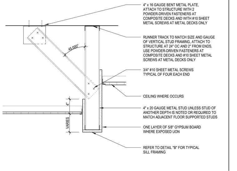
This assembly features a four-inch by twenty-gauge metal stud braced at a forty-five-degree angle to the overhead structure. The brace is secured to the structure using a four-inch by sixteen-gauge bent metal plate, fastened with two powder-driven fasteners at composite decks or number ten sheet metal screws at metal decks. The runner track matches the size and gauge of the vertical stud framing and is attached to the structure at twenty-four inches on center and two inches from the ends. The brace connects to the vertical stud using four three-quarter-inch number ten sheet metal screws at each end. Where exposed, the stud is finished with one layer of five-eighths-inch gypsum board unless otherwise noted.
RUNNER TRACK TO MATCH SIZE AND GAUGE OF VERTICAL STUD FRAMING, ATTACH TO STRUCTURE AT 24" OC AND 2" FROM ENDS. USE POWDER-DRIVEN FASTENERS AT COMPOSITE DECKS AND #10 SHEET METAL SCREWS AT METAL DECKS ONLY 3/4" #10 SHEET METAL SCREWS TYPICAL OF FOUR EACH END CEILING WHERE OCCURS 4" x 20 GAUGE METAL STUD UNLESS STUD OF ANOTHER DEPTH IS NOTED OR REQUIRED TO MATCH ADJACENT FLOOR SUPPORTED STUDS ONE LAYER OF 5/8" GYPSUM BOARD WHERE EXPOSED UON REFER TO DETAIL "B" FOR TYPICAL SILL FRAMING 4" VARIES 45.000°
Members view this detail in full resolution, download the CAD files (SVG, PDF), and can adapt it in the built-in CAD editor — export DXF, DWG, or PDF.
Start membership