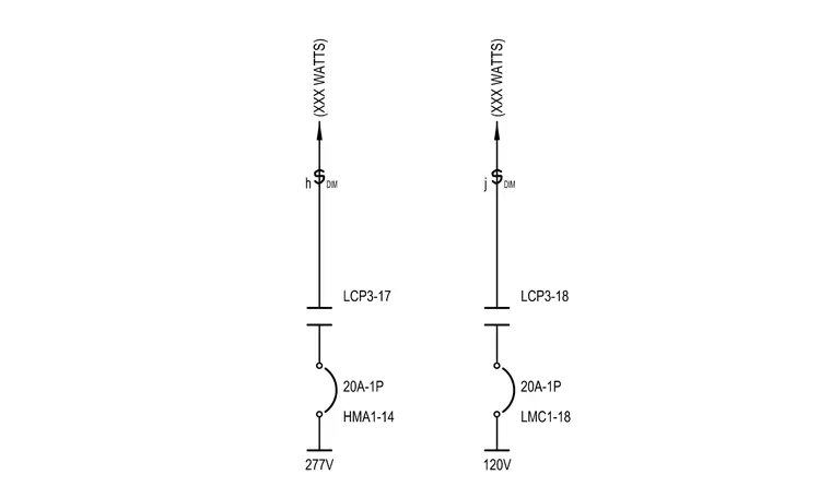
This lighting control wiring diagram outlines circuit connections for two separate lighting loads, indicating voltage supplies of 277V and 120V routed through twenty-amp single-pole switches. Each circuit maps the connection from the power source through lighting control panel channels labeled LCP3-17 and LCP3-18 to individual switch legs designated h and j. Wattage allowances are specified by placeholder values alongside circuit identifiers and load designations HMA1-14 and LMC1-18.
Members view this detail in full resolution, download the CAD files (SVG, PDF), and can adapt it in the built-in CAD editor — export DXF, DWG, or PDF.
Start membership