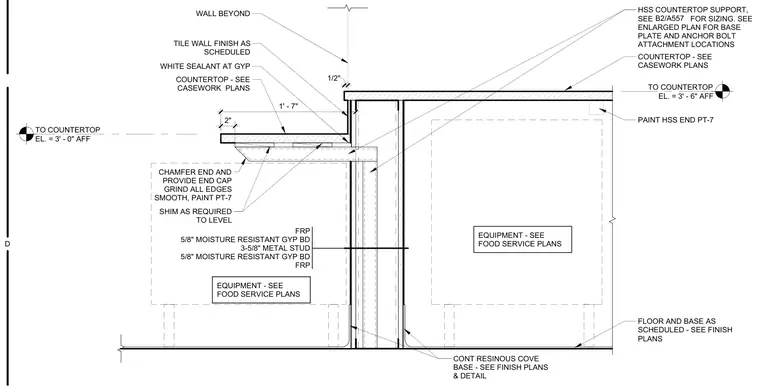
A multi-tier countertop assembly features high and low service levels at elevations 3'-6" and 3'-0" above finished floor. The supporting structure consists of 3-5/8 inch metal studs faced with 5/8 inch moisture resistant gypsum board and fiberglass reinforced plastic panels on both sides. A two-inch hollow structural section steel countertop support member is shammed as required to level, with its end chamfered, capped, and ground smooth prior to painting. White sealant is applied at the gypsum and countertop interface, and the assembly is finished with continuous resinous cove base at the floor.
TO COUNTERTOP EL. = 3' - 0" AFF TO COUNTERTOP EL. = 3' - 6" AFF WALL BEYOND EQUIPMENT - SEE FOOD SERVICE PLANS FRP 5/8" MOISTURE RESISTANT GYP BD 3-5/8" METAL STUD 5/8" MOISTURE RESISTANT GYP BD FRP FLOOR AND BASE AS SCHEDULED - SEE FINISH PLANS CONT RESINOUS COVE BASE - SEE FINISH PLANS & DETAIL PAINT HSS END PT-7 TILE WALL FINISH AS SCHEDULED 1/2" 1' - 7" COUNTERTOP - SEE CASEWORK PLANS EQUIPMENT - SEE FOOD SERVICE PLANS CHAMFER END AND PROVIDE END CAP GRIND ALL EDGES SMOOTH, PAINT PT-7 WHITE SEALANT AT GYP COUNTERTOP - SEE CASEWORK PLANS SHIM AS REQUIRED TO LEVEL 2" HSS COUNTERTOP SUPPORT, SEE FOR SIZING. SEE ENLARGED PLAN FOR BASE PLATE AND ANCHOR BOLT ATTACHMENT LOCATIONS B2/A557 D
Members view this detail in full resolution, download the CAD files (SVG, PDF), and can adapt it in the built-in CAD editor — export DXF, DWG, or PDF.
Start membership