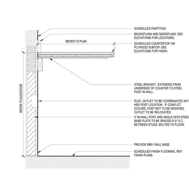
This assembly features a steel bracket extending from the underside of a scheduled countertop on a plywood subtop to a three-inch hollow structural section post concealed within a partition wall. The in-wall post and angle assembly includes a steel base plate and is bolted to the floor at six feet on center between studs. Electrical outlets must be coordinated with the hollow structural section post location, with the outlet relocated if a conflict occurs to avoid modifying the post. The partition includes a scheduled wall base and finish flooring as specified in the finish plans, with backsplash and sidesplash locations determined by the elevations.
REFER TO ELEVATION REFER TO PLAN SCHEDULED PARTITION SCHEDULED COUNTERTOP ON PLYWOOD SUBTOP. SEE ELEVATIONS FOR FINISH. STEEL BRACKET, EXTENDED FROM UNDERSIDE OF COUNTER TO STEEL POST IN WALL. ELEC. OUTLET TO BE COORDINATED WITH HSS POST LOCATION. IF CONFLICT OCCURS, POST NOT TO BE MODIFIED, OUTLET TO BE RELOCATED. PROVIDE RB01 WALL BASE SCHEDULED FINISH FLOORING, REF: FINISH PLANS 3" IN-WALL POST AND ANGLE WITH STEEL BASE PLATE TO BE SPACED 6'-0" O.C. BETWEEN STUDS. BOLTED TO FLOOR. BACKSPLASH AND SIDESPLASH, SEE ELEVATIONS FOR LOCATIONS.
Members view this detail in full resolution, download the CAD files (SVG, PDF), and can adapt it in the built-in CAD editor — export DXF, DWG, or PDF.
Start membership