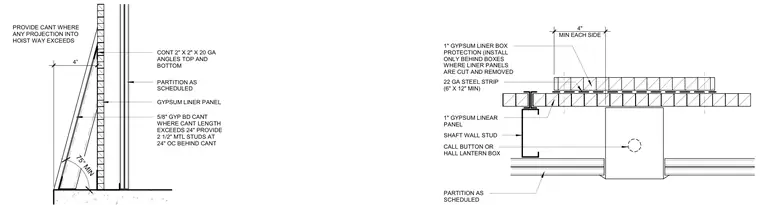
This elevator shaftwall detail shows the installation requirements for recessed fixtures such as call buttons or hall lanterns within a gypsum liner panel partition. Continuous two-inch by two-inch by twenty-gauge angles secure the assembly at the top and bottom. A one-inch gypsum liner box protection is installed behind electrical boxes where liner panels are cut and removed, supplemented by a twenty-two-gauge steel strip measuring at least six inches by twelve inches. Additionally, a five-eighths-inch gypsum board cant is provided where any projection into the hoistway exceeds five-eighths of an inch. Where cant lengths exceed twenty-four inches, two-and-a-half-inch metal studs are spaced at twenty-four inches on center behind the cant at a minimum seventy-five-degree angle.
MIN EACH SIDE 4" PARTITION AS SCHEDULED CALL BUTTON OR HALL LANTERN BOX 1" GYPSUM LINEAR PANEL 22 GA STEEL STRIP (6" X 12" MIN) 1" GYPSUM LINER BOX PROTECTION (INSTALL ONLY BEHIND BOXES WHERE LINER PANELS ARE CUT AND REMOVED SHAFT WALL STUD 75° MIN 4” PROVIDE CANT WHERE ANY PROJECTION INTO HOIST WAY EXCEEDS 5/8" GYP BD CANT WHERE CANT LENGTH EXCEEDS 24" PROVIDE 2 1/2" MTL STUDS AT 24" OC BEHIND CANT GYPSUM LINER PANEL PARTITION AS SCHEDULED CONT 2" X 2" X 20 GA ANGLES TOP AND BOTTOM
Members view this detail in full resolution, download the CAD files (SVG, PDF), and can adapt it in the built-in CAD editor — export DXF, DWG, or PDF.
Start membership