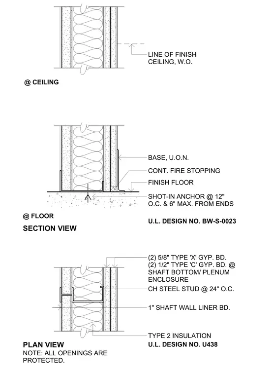
This assembly details a two-hour rated shaft wall featuring CH steel studs spaced at twenty-four inches on center with one-inch shaft wall liner board and type two insulation. The gypsum board configuration comprises two layers of five-eighths-inch Type X gypsum board, supplemented by two layers of one-half-inch Type C gypsum board at the shaft bottom and plenum enclosure. Floor and ceiling junctions incorporate continuous fire stopping and shot-in anchors spaced at twelve inches on center with a six-inch maximum from the ends. Construction complies with Underwriters Laboratories design numbers BW-S-0023 and U438.
PLAN VIEW @ FLOOR @ CEILING U.L. DESIGN NO. BW-S-0023 NOTE: ALL OPENINGS ARE PROTECTED. U.L. DESIGN NO. U438 LINE OF FINISH CEILING, W.O. SECTION VIEW BASE, U.O.N. CONT. FIRE STOPPING FINISH FLOOR SHOT-IN ANCHOR @ 12" O.C. & 6" MAX. FROM ENDS (2) 5/8" TYPE 'X' GYP. BD. (2) 1/2" TYPE 'C' GYP. BD. @ SHAFT BOTTOM/ PLENUM ENCLOSURE CH STEEL STUD @ 24" O.C. 1" SHAFT WALL LINER BD. TYPE 2 INSULATION
Members view this detail in full resolution, download the CAD files (SVG, PDF), and can adapt it in the built-in CAD editor — export DXF, DWG, or PDF.
Start membership