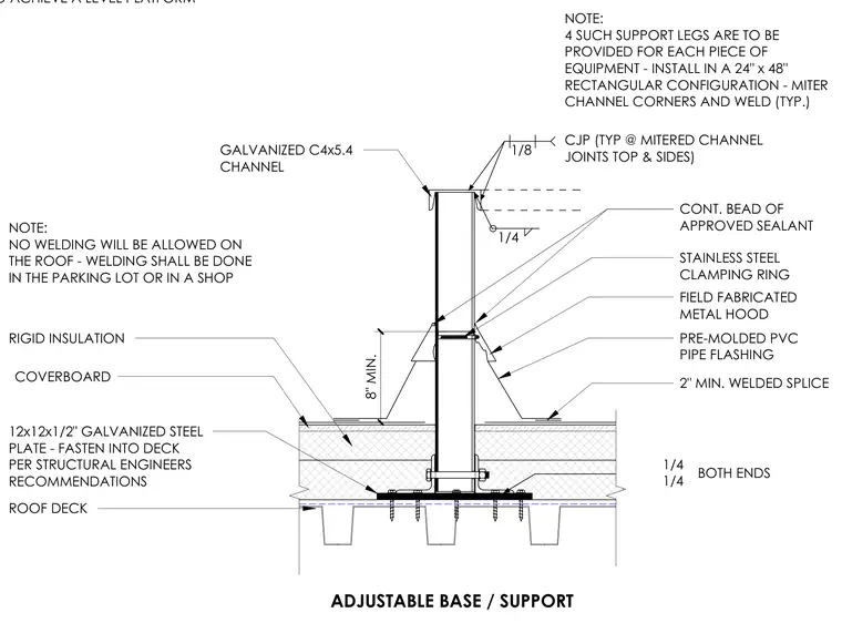
An equipment support leg is anchored to a roof deck assembly consisting of a roof deck, coverboard, and rigid insulation. A 12x12x1/2-inch galvanized steel plate is fastened into the deck per structural engineer recommendations and supports a galvanized C4x5.4 channel leg. Four such support legs are required for each piece of equipment, installed in a 24x48-inch rectangular configuration with mitered channel corners joined by one-eighth-inch complete joint penetration welds at the top and sides. A pre-molded polyvinyl chloride pipe flashing extends upward over the penetration, secured at the top with a stainless steel clamping ring and a continuous bead of approved sealant. A field-fabricated metal hood covers the base of the flashing, with a two-inch minimum welded splice. No welding is allowed on the roof; all welding must be performed in a parking lot or shop.
ADJUSTABLE BASE / SUPPORT ROOF DECK 1/4 BOTH ENDS AS REQ'D. TO ACHIEVE A LEVEL PLATFORM NOTE: 4 SUCH SUPPORT LEGS ARE TO BE PROVIDED FOR EACH PIECE OF EQUIPMENT - INSTALL IN A 24" x 48" RECTANGULAR CONFIGURATION - MITER CHANNEL CORNERS AND WELD (TYP.) CONT. BEAD OF APPROVED SEALANT STAINLESS STEEL CLAMPING RING FIELD FABRICATED METAL HOOD PRE-MOLDED PVC PIPE FLASHING 2" MIN. WELDED SPLICE 12x12x1/2" GALVANIZED STEEL PLATE - FASTEN INTO DECK PER STRUCTURAL ENGINEERS RECOMMENDATIONS RIGID INSULATION 1/4 1/4 8" MIN. 1/8 CJP (TYP @ MITERED CHANNEL JOINTS TOP & SIDES) GALVANIZED C4x5.4 CHANNEL NOTE: NO WELDING WILL BE ALLOWED ON THE ROOF - WELDING SHALL BE DONE IN THE PARKING LOT OR IN A SHOP COVERBOARD
Members view this detail in full resolution, download the CAD files (SVG, PDF), and can adapt it in the built-in CAD editor — export DXF, DWG, or PDF.
Start membership