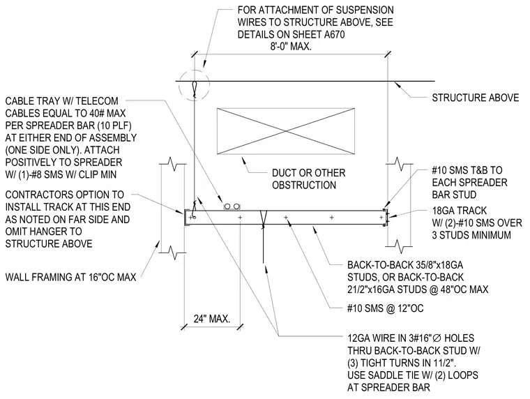
A corridor spreader bar assembly bridges around ceiling obstructions such as ducts or piping. The assembly consists of back-to-back 3-5/8 inch 18-gauge studs or back-to-back 2-1/2 inch 16-gauge studs spaced at a maximum of 48 inches on center. Suspension is achieved using 12-gauge wire routed through 3/16-inch diameter holes in the back-to-back studs with three tight turns within 1-1/2 inches, secured with a saddle tie having two loops at the spreader bar. Cable trays carrying telecom cables up to 40 pounds maximum per spreader bar attach positively using a minimum of one number 8 self-drilling metal screw with a clip. End connections utilize an 18-gauge track fastened with two number 16 self-drilling metal screws over three studs minimum, with number 10 screws top and bottom to each spreader bar stud.
8'-0" MAX. 24" MAX. FOR ATTACHMENT OF SUSPENSION WIRES TO STRUCTURE ABOVE, SEE DETAILS ON SHEET A670 CABLE TRAY W/ TELECOM CABLES EQUAL TO 40# MAX PER SPREADER BAR (10 PLF) AT EITHER END OF ASSEMBLY (ONE SIDE ONLY). ATTACH POSITIVELY TO SPREADER W/ (1)-#8 SMS W/ CLIP MIN CONTRACTORS OPTION TO INSTALL TRACK AT THIS END AS NOTED ON FAR SIDE AND OMIT HANGER TO STRUCTURE ABOVE WALL FRAMING AT 16"OC MAX DUCT OR OTHER OBSTRUCTION STRUCTURE ABOVE #10 SMS T&B TO EACH SPREADER BAR STUD 18GA TRACK W/ (2)-#10 SMS OVER 3 STUDS MINIMUM BACK-TO-BACK 35/8"x18GA STUDS, OR BACK-TO-BACK 21/2"x16GA STUDS @ 48"OC MAX #10 SMS @ 12"OC 12GA WIRE IN 3#16" ∅ HOLES THRU BACK-TO-BACK STUD W/ (3) TIGHT TURNS IN 11/2". USE SADDLE TIE W/ (2) LOOPS AT SPREADER BAR
Members view this detail in full resolution, download the CAD files (SVG, PDF), and can adapt it in the built-in CAD editor — export DXF, DWG, or PDF.
Start membership