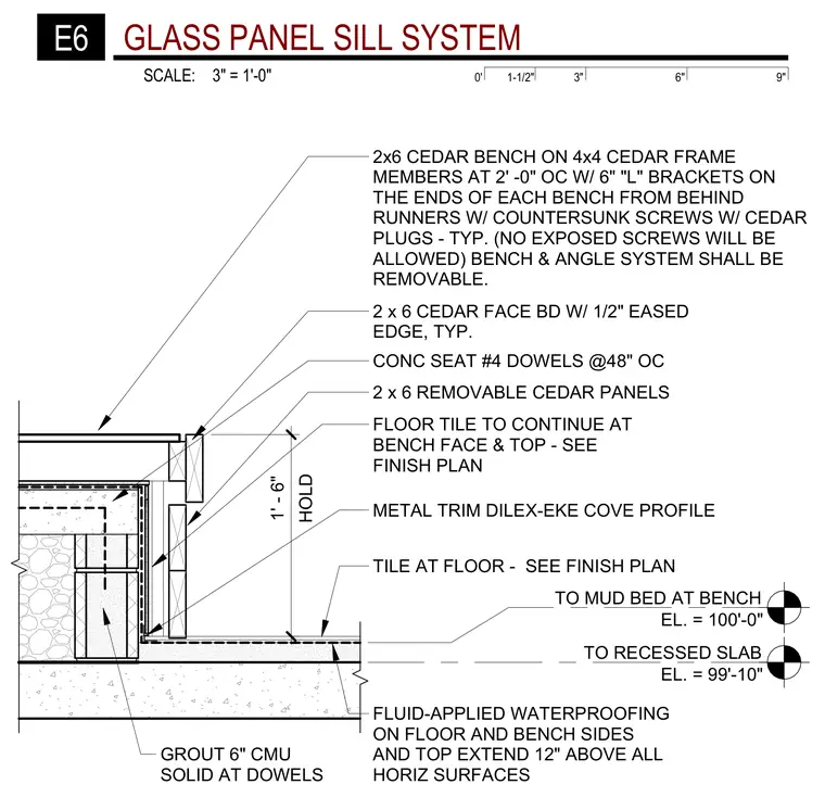
A sauna bench assembly is supported by a concrete seat and concrete masonry unit structure, featuring removable cedar panels and custom framing. The concrete seat incorporates number four reinforcing dowels spaced at forty-eight inches on center, with six-inch concrete masonry units solidly grouted at dowel locations. Fluid-applied waterproofing is applied across the floor and bench surfaces, extending twelve inches above all horizontal transitions. The bench consists of two-by-six cedar face boards and framing members spaced at two feet on center, secured with six-inch L-brackets and countersunk screws plugged with cedar to conceal all fasteners. Floor tile continues across the bench face and top, terminated with a metal Schluter-Dilex-EKE cove profile at the base. The assembly rests on a recessed concrete slab with elevations coordinated to the mud bed.
TO MUD BED AT BENCH EL. = 100'-0" TO RECESSED SLAB EL. = 99'-10" 2 x 6 CEDAR FACE BD W/ 1/2" EASED EDGE, TYP. 2x6 CEDAR BENCH ON 4x4 CEDAR FRAME MEMBERS AT 2' -0" OC W/ 6" "L" BRACKETS ON THE ENDS OF EACH BENCH FROM BEHIND RUNNERS W/ COUNTERSUNK SCREWS W/ CEDAR PLUGS - TYP. (NO EXPOSED SCREWS WILL BE ALLOWED) BENCH & ANGLE SYSTEM SHALL BE REMOVABLE. FLOOR TILE TO CONTINUE AT BENCH FACE & TOP - SEE FINISH PLAN 2 x 6 REMOVABLE CEDAR PANELS FLUID-APPLIED WATERPROOFING ON FLOOR AND BENCH SIDES AND TOP EXTEND 12" ABOVE ALL HORIZ SURFACES TILE AT FLOOR - SEE FINISH PLAN GROUT 6" CMU SOLID AT DOWELS CONC SEAT #4 DOWELS @48" OC HOLD 1' - 6" METAL TRIM DILEX-EKE COVE PROFILE 0' 6" 9" 3" 1-1/2" SCALE: 3" = 1'-0" E6 GLASS PANEL SILL SYSTEM
Members view this detail in full resolution, download the CAD files (SVG, PDF), and can adapt it in the built-in CAD editor — export DXF, DWG, or PDF.
Start membership