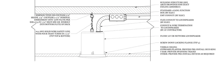
A flush-mounted 70V or network loudspeaker in a gypsum board or plaster ceiling connects electrically and mounts to the overhead building structure using a Simpson Titen HD coupler with a 2-1/2 inch nominal embedment into the low flute of the deck, paired with a 1/4 inch Hilti MW-EB eyebolt in the bottom flute. A number 12 American Wire Gauge solid wire safety line provides secondary support with four tight turns in 1-1/2 inches at both the top and bottom. Electrical power and signal are routed via an electrical metallic tubing conduit into a standard single-gang junction box, continuing through flexible conduit to the loudspeaker housing. The loudspeaker is secured with four screw-down locking flanges behind the finished ceiling plane, requiring a pre-installed mud ring for gypsum board or spanning tracks for a T-bar ceiling system.
SIMPSON TITEN HD COUPLER (1/4" SHANK, 1/4" COUPLER) 2 1/2" NOMINAL EMBEDMENT INTO LOW FLUTE PER ESR-2713 W/ 1/4" HILTI MW-EB EYEBOLT INTO BOTTOM FLUTE OF DECK #12 AWG SOLID WIRE SAFETY LINE WITH FOUR TIGHT TURNS IN 1-1/2" (TYP TOP & BOTTOM) BUILDING STRUCTURE (SEE ARCH DRAWINGS FOR EXACT CEILING ASSEMBLY) STANDARD 1-GANG JUNCTION BOX (BY ELEC) EMT CONDUIT (BY ELEC) FLEX CONDUIT TO LOUDSPEAKER (BY ELEC) CONDUIT & WIRE TERMINATION TO LOUDSPEAKER (BY AV CONTRACTOR) FLUSH 70V OR NETWORK LOUDSPEAKER SCREW-DOWN LOCKING FLANGE (TYP 4) VISIBLE CEILING GYPBOARD/PLASTER: PROVIDE PRE-INSTALL MUD RING T-BAR: PROVIDE SPANNING TRACKS OTHER: PROVIDE PRE-INSTALL DEVICES AS REQUIRED
Members view this detail in full resolution, download the CAD files (SVG, PDF), and can adapt it in the built-in CAD editor — export DXF, DWG, or PDF.
Start membership