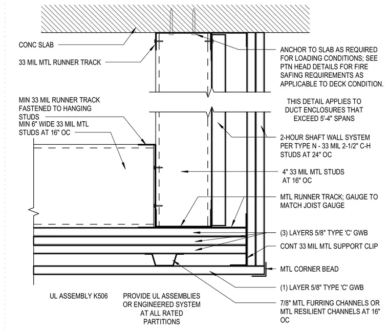
This two-hour rated horizontal shaft wall enclosure applies to duct enclosures exceeding five feet four inches in spans and attaches directly to an overhead concrete slab. A continuous thirty-three mil metal support clip and runner tracks anchor the assembly to the slab as required for loading conditions. The framing consists of thirty-three mil metal studs spaced at sixteen inches on center alongside a two-hour shaft wall system using twenty-five-inch C-H studs at twenty-four inches on center. The underside is finished with three layers of five-eighths-inch Type C gypsum wallboard on the interior face and one layer on the exterior, supported by seven-eighths-inch metal furring channels or resilient channels at sixteen inches on center with a metal corner bead at the edge. UL Assembly K506 governs the fire-rated construction.
(3) LAYERS 5/8" TYPE 'C' GWB MTL RUNNER TRACK; GAUGE TO MATCH JOIST GAUGE PROVIDE UL ASSEMBLIES OR ENGINEERED SYSTEM AT ALL RATED PARTITIONS 4" 33 MIL MTL STUDS AT 16" OC 7/8" MTL FURRING CHANNELS OR MTL RESILIENT CHANNELS AT 16" OC (1) LAYER 5/8" TYPE 'C' GWB ANCHOR TO SLAB AS REQUIRED FOR LOADING CONDITIONS; SEE PTN HEAD DETAILS FOR FIRE SAFING REQUIREMENTS AS APPLICABLE TO DECK CONDITION. UL ASSEMBLY K506 CONT 33 MIL MTL SUPPORT CLIP 2-HOUR SHAFT WALL SYSTEM PER TYPE N - 33 MIL 2-1/2" C-H STUDS AT 24" OC MIN 33 MIL RUNNER TRACK FASTENED TO HANGING STUDS 33 MIL MTL RUNNER TRACK MIN 6" WIDE 33 MIL MTL STUDS AT 16" OC CONC SLAB MTL CORNER BEAD THIS DETAIL APPLIES TO DUCT ENCLOSURES THAT EXCEED 5'-4" SPANS
Members view this detail in full resolution, download the CAD files (SVG, PDF), and can adapt it in the built-in CAD editor — export DXF, DWG, or PDF.
Start membership