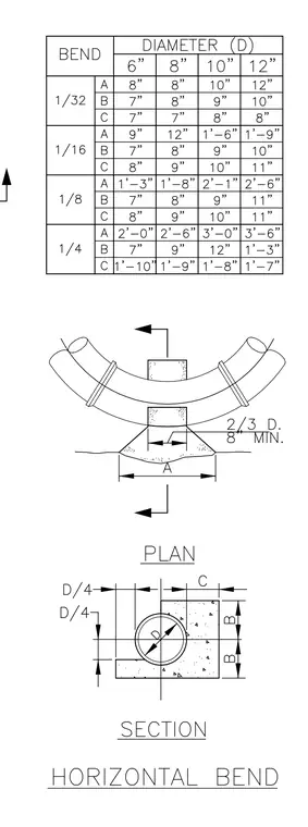
A sizing table, plan view, and section view define a horizontal bend thrust block. The table lists dimensions A, B, and C corresponding to bend angles of 1/32, 1/16, 1/8, and 1/4 across pipe diameters of 6, 8, 10, and 12 inches. The plan and section views detail the concrete placement against the pipe bend with a minimum thickness of two-thirds of the diameter D or 8 inches. Dimension callouts define the bearing area and clearance parameters for the concrete thrust restraint.
Members view this detail in full resolution, download the CAD files (SVG, PDF), and can adapt it in the built-in CAD editor — export DXF, DWG, or PDF.
Start membership