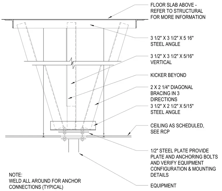
Equipment is suspended below the floor slab above with a three-and-a-half by three-and-a-half by five-sixteenths-inch vertical steel angle and an equipment kicker beyond. Three-and-a-half by three-and-a-half by five-sixteenths-inch steel angles and three-and-a-half by two-and-a-half by five-sixteenths-inch steel angles frame the assembly, supplemented by two by two-and-a-quarter-inch diagonal bracing in three directions. A half-inch steel plate with anchoring bolts secures the equipment connection, verified against the specific equipment configuration. The ceiling finish is installed as scheduled and coordinated with the reflected ceiling plan. Anchor connections feature welds all around as typical, while floor slab attachment is coordinated with structural documents.
NOTE: WELD ALL AROUND FOR ANCHOR CONNECTIONS (TYPICAL) EQUIPMENT KICKER BEYOND 3 1/2" X 3 1/2" X 5/16" VERTICAL 3 1/2" X 3 1/2" X 5 16" STEEL ANGLE FLOOR SLAB ABOVE - REFER TO STRUCTURAL FOR MORE INFORMATION 1/2" STEEL PLATE PROVIDE PLATE AND ANCHORING BOLTS AND VERIFY EQUIPMENT CONFIGURATION & MOUNTING DETAILS CEILING AS SCHEDULED, SEE RCP 3 1/2" X 2 1/2" X 5/15" STEEL ANGLE 2 X 2 1/4" DIAGONAL BRACING IN 3 DIRECTIONS
Members view this detail in full resolution, download the CAD files (SVG, PDF), and can adapt it in the built-in CAD editor — export DXF, DWG, or PDF.
Start membership