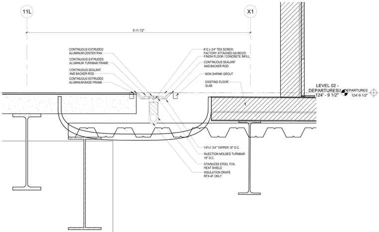
A floor expansion joint assembly is installed between concrete floor slabs supported by structural steel framing at Level 02. The assembly features a continuous extruded aluminum center pan and turnbar frame, secured with number twelve by three-quarter inch self-tapping screws and one-quarter by one and three-quarter inch tapcon anchors spaced eighteen inches on center. Non-shrink grout fills the recess around the base frames, backed by continuous sealant and backer rods at the floor finish transitions. Below the joint, an injection-molded turnbar supports a stainless steel foil heat shield and an RFX-4F insulation drape hung between the structural steel beams.
LEVEL 02 - DEPARTURES 124'-9 1/2" 11L X1 5'-11 1/2" NON SHRINK GROUT CONTINUOUS SEALANT AND BACKER ROD FINISH FLOOR / CONCRETE INFILL #12 x 3/4" TEK SCREW, FACTORY ATTACHED AS REQ'D EXISTING FLOOR SLAB 1/4"x1 3/4" TAPPER 18" O.C. INJECTION MOLDED TURNBAR 18" O.C. CONTINUOUS EXTRUDED ALUMINUM TURNBAR FRAME INSULATION DRAPE RFX-4F ONLY CONTINUOUS SEALANT AND BACKER ROD CONTINUOUS EXTRUDED ALUMINUM BASE FRAME CONTINUOUS EXTRUDED ALUMINUM CENTER PAN STAINLESS STEEL FOIL HEAT SHIELD LEVEL 02 - DEPARTURES 124' - 9 1/2"
Members view this detail in full resolution, download the CAD files (SVG, PDF), and can adapt it in the built-in CAD editor — export DXF, DWG, or PDF.
Start membership