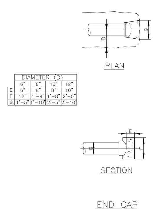
Plan and section configurations of a pipe end cap assembly accompany a sizing table for various pipe diameters. Nominal diameters D of six inches, eight inches, ten inches, and twelve inches cross-reference with corresponding dimensions E, F, and G. The pipe aligns with the end cap component in plan, and the section view indicates the profile and dimensional parameters E and F. Dimension G controls the width of the cap in plan.
Members view this detail in full resolution, download the CAD files (SVG, PDF), and can adapt it in the built-in CAD editor — export DXF, DWG, or PDF.
Start membership