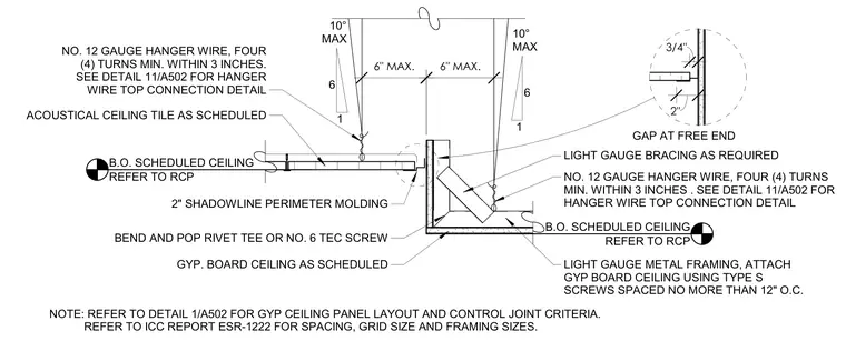
A transition connects a gypsum board ceiling and an acoustical ceiling tile system meeting at a two-inch shadowline perimeter molding. The acoustical ceiling tile is supported by a grid system suspended with number twelve gauge hanger wires featuring a minimum of four turns within three inches. The gypsum board ceiling is framed with light gauge metal framing and attached using type S screws spaced no more than twelve inches on center. Additional light gauge bracing is provided as required, secured with number twelve gauge hanger wires. A gap is maintained at the free end of the acoustical tile edge against the shadowline molding.
NO. 12 GAUGE HANGER WIRE, FOUR (4) TURNS MIN. WITHIN 3 INCHES. SEE DETAIL 11/A502 FOR HANGER WIRE TOP CONNECTION DETAIL 2" SHADOWLINE PERIMETER MOLDING ACOUSTICAL CEILING TILE AS SCHEDULED GYP. BOARD CEILING AS SCHEDULED B.O. SCHEDULED CEILING REFER TO RCP GAP AT FREE END LIGHT GAUGE BRACING AS REQUIRED 3/4" 2" 6" MAX. 6" MAX. LIGHT GAUGE METAL FRAMING, ATTACH GYP BOARD CEILING USING TYPE S SCREWS SPACED NO MORE THAN 12" O.C. BEND AND POP RIVET TEE OR NO. 6 TEC SCREW NO. 12 GAUGE HANGER WIRE, FOUR (4) TURNS MIN. WITHIN 3 INCHES . SEE DETAIL 11/A502 FOR HANGER WIRE TOP CONNECTION DETAIL 1 6 10° MAX 1 6 10° MAX B.O. SCHEDULED CEILING REFER TO RCP NOTE: REFER TO DETAIL 1/A502 FOR GYP CEILING PANEL LAYOUT AND CONTROL JOINT CRITERIA. REFER TO ICC REPORT ESR-1222 FOR SPACING, GRID SIZE AND FRAMING SIZES.
Members view this detail in full resolution, download the CAD files (SVG, PDF), and can adapt it in the built-in CAD editor — export DXF, DWG, or PDF.
Start membership