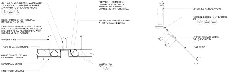
An air terminal or light fixture with a maximum weight of fifty-six pounds hangs from a ceiling assembly featuring one-and-a-half-inch by sixteen-gauge main runners and seven-eighths-inch by twenty-gauge furring channels, finished with five-eighths-inch gypsum board. Two twelve-gauge slack safety hanger wires at diagonally opposite corners anchor directly to the structure above. Additional U-channels provide support as required, while direct support by the furring channel is prohibited. A five-eighths-inch diameter expansion anchor secures a twelve-gauge brace wire featuring four turns at each end with a maximum half-inch offset.
5/8" DIA. EXPANSION ANCHOR FOR CONNECTION TO STRUCTURE SEE 4 TURNS @ BRACE WIRES, TYP. @ EACH END MAX. 1/2" MAX. 1/2" A871 7 A874 6 A875 1 MAX. 1 1/2" 12 GA. WIRE A871 6 LIGHT FIXTURE OR AIR TERMINAL MAX WEIGHT = 56 LBS. EXCEPTION:" FIXTURES GREATER THAN 2'-0" x 4'-0" WEIGHING MORE THAN 56 LBS. REQUIRE A 12 GA. SLACK SAFETY WIRE HANGER AT EACH CORNER. 1 1/2" x 16 GA. MAIN RUNNER CROSS RUNNER, 7/8" x 20 GA. FURRING CHANNEL (2) 12 GA. SLACK SAFETY HANGER WIRE AT DIAGONALLY OPPOSITE CORNERS ANCHORED TO STRUCTURE ABOVE PROVIDE (1) OR MORE U- CHANNELS AS REQUIRED. SUPPORT BY FURRING CHANNEL IS NOT PERMITTED. ADDITIONAL FURRING CHANNEL AT FIXTURE AS REQUIRED FINISH PER SCHEDULE 5/8" GYPSUM BOARD HANGER WIRE A874 2 A875 2 A875 3 SADDLE TIES SEE SIM.
Members view this detail in full resolution, download the CAD files (SVG, PDF), and can adapt it in the built-in CAD editor — export DXF, DWG, or PDF.
Start membership