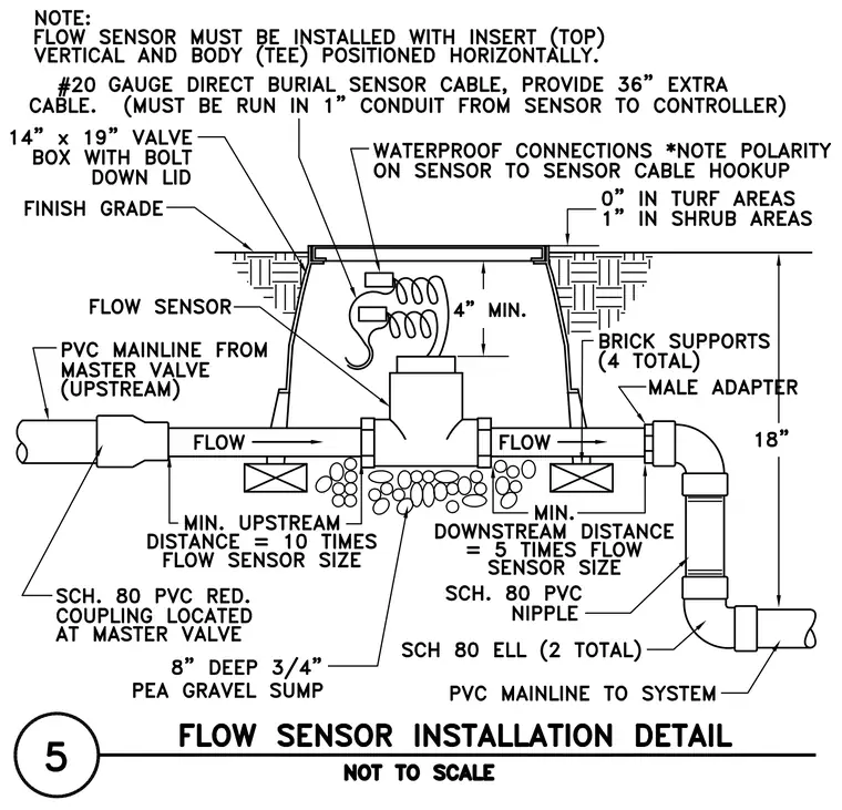
The irrigation flow sensor is housed within a fourteen by nineteen inch valve box with a bolt-down lid, set flush at finish grade with zero inches in turf areas and one inch in shrub areas. The flow sensor bodytee is positioned horizontally with the insert installed at the top, connected to the polyvinyl chloride mainline coming upstream from the master valve and continuing downstream to the system. A schedule eighty polyvinyl chloride reducer coupling is located at the master valve, while the downstream side features a schedule eighty polyvinyl chloride nipple and two schedule eighty elbows. The assembly sits on an eight-inch deep three-quarter-inch pea gravel sump with four brick supports beneath the valve box. Minimum clearances require an upstream distance equal to ten times the flow sensor size and a downstream distance equal to five times the flow sensor size, with a minimum of four inches of clearance above the sensor components. A number twenty gauge direct burial sensor cable with thirty-six inches of extra cable is run in a one-inch conduit from the sensor to the controller with waterproof connections.
Members view this detail in full resolution, download the CAD files (SVG, PDF), and can adapt it in the built-in CAD editor — export DXF, DWG, or PDF.
Start membership