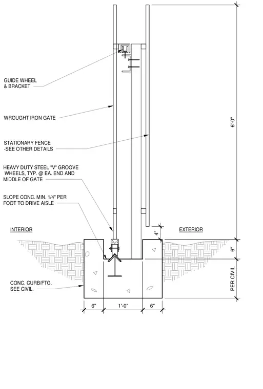
A wrought iron gate is supported by heavy-duty steel V-groove wheels located at each end and the middle of the gate, rolling on an inverted track embedded in a concrete curb and footing. An exterior guide wheel and bracket assembly stabilizes the top of the gate against a stationary fence. The adjacent concrete slopes a minimum of 1/4 inch per foot toward the drive aisle, with the concrete curb and footing sized per civil engineering drawings.
EXTERIOR GUIDE WHEEL & BRACKET HEAVY DUTY STEEL "V" GROOVE WHEELS, TYP. @ EA. END AND MIDDLE OF GATE INTERIOR SLOPE CONC. MIN. 1/4" PER FOOT TO DRIVE AISLE CONC. CURB/FTG. SEE CIVIL. WROUGHT IRON GATE STATIONARY FENCE -SEE OTHER DETAILS 6" 1'-0" 6" 6" PER CIVIL 6'-0" 4"
Members view this detail in full resolution, download the CAD files (SVG, PDF), and can adapt it in the built-in CAD editor — export DXF, DWG, or PDF.
Start membership