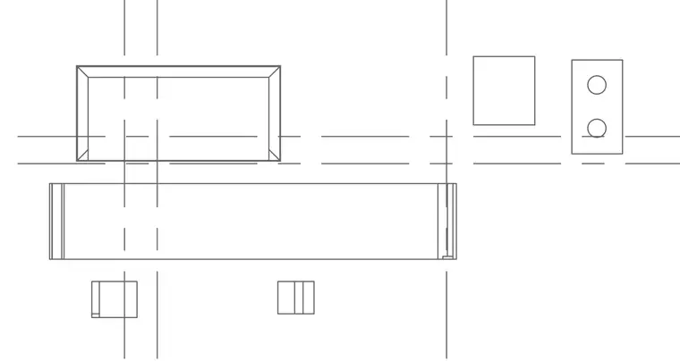
This drawing outlines architectural framing components, alignment grids, and connection plates. The layout details relative positioning and spatial coordination between members. Fastener and plate locations are established relative to primary reference lines.
Members view this detail in full resolution, download the CAD files (SVG, PDF), and can adapt it in the built-in CAD editor — export DXF, DWG, or PDF.
Start membership