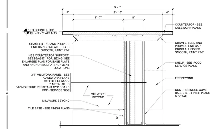
A cafe service counter is supported by a hollow structural section countertop support post that anchors to the floor slab. The counter assembly features a three-foot-six-inch wide top with chamfered ends and painted edge caps. The dwarf wall backing the support post is constructed of six-inch metal studs faced with five-eighths-inch fire-retardant plywood, five-eighths-inch moisture-resistant gypsum board, and fiberglass reinforced plastic on the service side. Millwork panels and shelving occur beyond, finished with a continuous resinous cove base on the service side and a tile base on the patron side.
TO COUNTERTOP EL. = 3' - 0" AFF MAX COUNTERTOP - SEE CASEWORK PLANS TILE BASE - SEE FINISH PLANS 3' - 6" HSS COUNTERTOP SUPPORT, SEE FOR SIZING. SEE ENLARGED PLAN FOR BASE PLATE AND ANCHOR BOLT ATTACHMENT LOCATIONS 3/4" MILLWORK PANEL - SEE CASEWORK PLANS 5/8" FRT PLYWOOD 6" METAL STUD 5/8" MOISTURE RESISTANT GYP BOARD FRP - SERVICE SIDE 6" MILLWORK BEYOND FRP BEYOND CONT RESINOUS COVE BASE - SEE FINISH PLANS & DETAIL 1' - 7" 8" SHELF - SEE FOOD SERVICE PLANS 4" 2' - 10" 4" MILLWORK BEYOND B2/A557 CHAMFER END AND PROVIDE END CAP GRIND ALL EDGES SMOOTH, PAINT PT-7 CHAMFER END AND PROVIDE END CAP GRIND ALL EDGES SMOOTH, PAINT PT-7 A
Members view this detail in full resolution, download the CAD files (SVG, PDF), and can adapt it in the built-in CAD editor — export DXF, DWG, or PDF.
Start membership