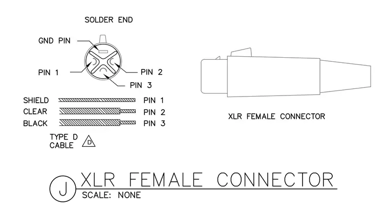
Pin 1, pin 2, pin 3, and the ground pin are designated on the solder end pin configuration of an XLR female connector. The shield connects to pin 1, the clear conductor connects to pin 2, and the black conductor connects to pin 3 using a Type D cable, per the wiring instructions.
Members view this detail in full resolution, download the CAD files (SVG, PDF), and can adapt it in the built-in CAD editor — export DXF, DWG, or PDF.
Start membership