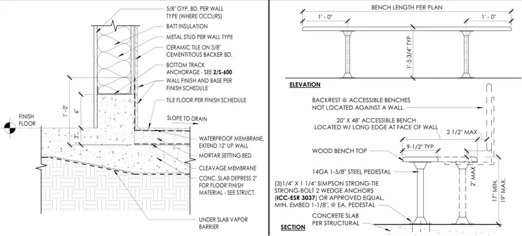
An accessible wood bench is anchored to a depressed concrete slab alongside a metal stud partition with ceramic tile finishes. The wood bench top is supported by 14-gauge, 1-5/8-inch steel pedestals anchored to the concrete slab using three 1/4-inch by 1-1/4-inch wedge anchors per pedestal with a minimum embedment of 1-1/8 inches. The concrete slab is depressed 2 inches for the floor finish material and is protected by a waterproof membrane extending 12 inches up the wall over a mortar setting bed and cleavage membrane, with an under-slab vapor barrier below. The adjacent wall assembly consists of metal studs with batt insulation and 5/8-inch gypsum board on one side and 5/8-inch cementitious backer board with ceramic tile on the other.
BENCH LENGTH PER PLAN 1' - 0" 9-1/2" TYP LOCATED W/ LONG EDGE AT FACE OF WALL 20" X 48" ACCESSIBLE BENCH 2 1/2" MAX 19" MAX. 17" MIN. BACKREST @ ACCESSIBLE BENCHES NOT LOCATED AGAINST A WALL 1' - 0" ELEVATION 14GA 1-5/8" STEEL PEDESTAL WOOD BENCH TOP 1'-5 3/4" TYP (3)1/4" X 1 1/4" SIMPSON STRONG-TIE STRONG-BOLT 2 WEDGE ANCHORS ( ICC-ESR 3037 ) OR APPROVED EQUAL, MIN. EMBED 1-1/8", @ EA. PEDESTAL SECTION CONCRETE SLAB PER STRUCTURAL 2" MAX 3" 6" 5/8" GYP. BD. PER WALL TYPE (WHERE OCCURS) BATT INSULATION METAL STUD PER WALL TYPE CERAMIC TILE ON 5/8" CEMENTITIOUS BACKER BD. WALL FINISH AND BASE PER FINISH SCHEDULE TILE FLOOR PER FINISH SCHEDULE WATERPROOF MEMBRANE, EXTEND 12" UP WALL MORTAR SETTING BED CLEAVAGE MEMBRANE CONC. SLAB DEPRESS 2" FOR FLOOR FINISH MATERIAL - SEE STRUCT. BOTTOM TRACK ANCHORAGE - SEE 2/S-600 UNDER SLAB VAPOR BARRIER SLOPE TO DRAIN 1' - 0" FINISH FLOOR
Members view this detail in full resolution, download the CAD files (SVG, PDF), and can adapt it in the built-in CAD editor — export DXF, DWG, or PDF.
Start membership