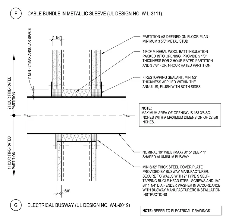
This plan detail shows a nominal nineteen-inch wide by five-inch deep I-shaped aluminum busway penetrating a minimum three-and-five-eighths-inch metal stud partition. The annular space between one and two inches is packed with four pcf mineral wool batt insulation, requiring a thickness of five and one-eighth inches for two-hour rated partitions and three and seven-eighths inches for one-hour rated partitions. Firestopping sealant with a minimum thickness of one-half inch is applied flush with both sides within the annulus. A minimum three-thirty-seconds-inch thick steel cover plate provided by the busway manufacturer is secured to the walls using two-inch Type S self-tapping bugle-head steel screws and one-quarter-inch by one-and-one-quarter-inch diameter fender washers. The maximum area of the opening is limited to one hundred fifty-eight and three-eighths square inches with a maximum dimension of twenty-two and five-eighths inches.
PARTITION AS DEFINED ON FLOOR PLAN - MINIMUM 3 5/8" METAL STUD G ELECTRICAL BUSWAY (UL DESIGN NO. W-L-6019) 4 PCF MINERAL WOOL BATT INSULATION PACKED INTO OPENING. PROVIDE 5 1/8" THICKNESS FOR 2-HOUR RATED PARTITION AND 3 7/8" FOR 1-HOUR RATED PARTITION FIRESTOPPING SEALANT, MIN 1/2" THICKNESS APPLIED WITHIN THE ANNULUS, FLUSH WITH BOTH SIDES 1" MIN - 2" MAX ANNULAR SPACE 1 HOUR FIRE-RATED PARTITION 2 HOUR FIRE-RATED PARTITION 5/8" 1 1/4" F CABLE BUNDLE IN METALLIC SLEEVE (UL DESIGN NO. W-L-3111) NOMINAL 19" WIDE (MAX) BY 5" DEEP "I" SHAPED ALUMINUM BUSWAY MIN 3/32" THICK STEEL COVER PLATE PROVIDED BY BUSWAY MANUFACTURER. SECURE TO WALLS WITH 2" TYPE S SELF- TAPPING BUGLE-HEAD STEEL SCREWS AND 1/4" BY 1 1/4" DIA FENDER WASHER IN ACCORDANCE WITH BUSWAY MANUFACTURERS INSTALLATION INSTRUCTIONS NOTE: REFER TO ELECTRICAL DRAWINGS NOTE: MAXIMUM AREA OF OPENING IS 158 3/8 SQ INCHES WITH A MAXIMUM DIMENSION OF 22 5/8 INCHES.
Members view this detail in full resolution, download the CAD files (SVG, PDF), and can adapt it in the built-in CAD editor — export DXF, DWG, or PDF.
Start membership