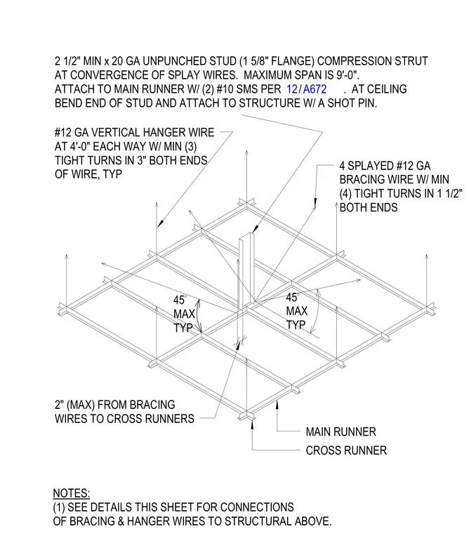
Suspended acoustical ceiling grids are stabilized against lateral loads using four splayed number twelve gauge bracing wires paired with a two and a half inch minimum by twenty gauge unpunched stud compression strut. The splayed bracing wires feature a minimum of four tight turns in one and a half inches at both ends and are positioned a maximum of two inches from the cross runners. The compression strut has a maximum span of nine feet, attaches to the main runner with two number ten sheet metal screws, and bends at the ceiling to anchor directly to the structure with a shot pin. Vertical support is provided by number twelve gauge hanger wires spaced at four feet each way with a minimum of three tight turns in three inches at both ends. Bracing wires are installed at a maximum angle of forty-five degrees typical.
MAIN RUNNER CROSS RUNNER 4 SPLAYED #12 GA BRACING WIRE W/ MIN (4) TIGHT TURNS IN 1 1/2" BOTH ENDS 2 1/2" MIN x 20 GA UNPUNCHED STUD (1 5/8" FLANGE) COMPRESSION STRUT AT CONVERGENCE OF SPLAY WIRES. MAXIMUM SPAN IS 9'-0". ATTACH TO MAIN RUNNER W/ (2) #10 SMS PER . AT CEILING BEND END OF STUD AND ATTACH TO STRUCTURE W/ A SHOT PIN. 2" (MAX) FROM BRACING WIRES TO CROSS RUNNERS NOTES: (1) SEE DETAILS THIS SHEET FOR CONNECTIONS OF BRACING & HANGER WIRES TO STRUCTURAL ABOVE. 45 MAX TYP 45 MAX TYP #12 GA VERTICAL HANGER WIRE AT 4'-0" EACH WAY W/ MIN (3) TIGHT TURNS IN 3" BOTH ENDS OF WIRE, TYP / 12 A672
Members view this detail in full resolution, download the CAD files (SVG, PDF), and can adapt it in the built-in CAD editor — export DXF, DWG, or PDF.
Start membership