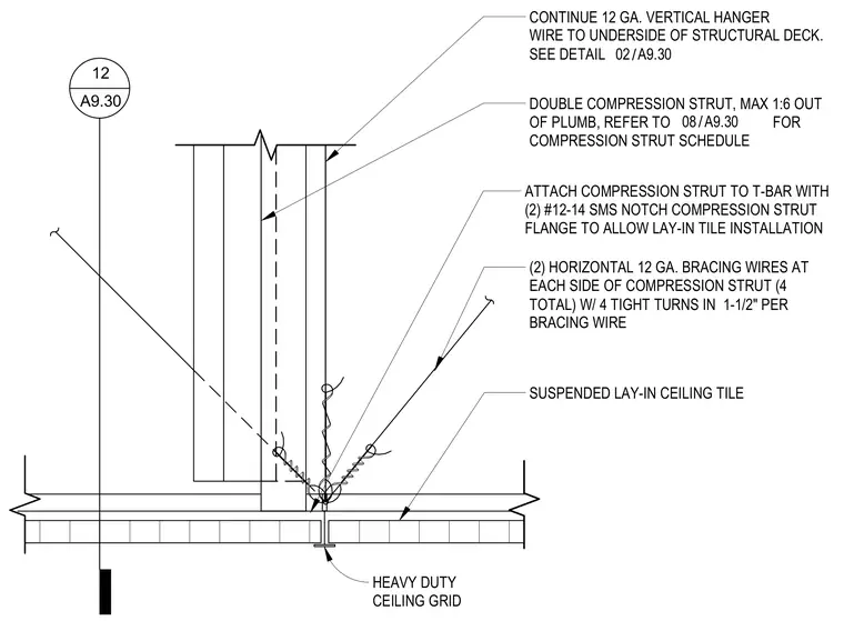
A suspended lay-in ceiling grid connects to a double compression strut secured by two number twelve by fourteen sheet metal screws. The compression strut flange is notched to allow lay-in tile installation. Four horizontal twelve-gauge bracing wires are attached to each side of the compression strut with four tight turns in one and a half inches per wire. A twelve-gauge vertical hanger wire continues from the grid to the underside of the structural deck.
CONTINUE 12 GA. VERTICAL HANGER WIRE TO UNDERSIDE OF STRUCTURAL DECK. SEE DETAIL DOUBLE COMPRESSION STRUT, MAX 1:6 OUT OF PLUMB, REFER TO FOR COMPRESSION STRUT SCHEDULE (2) HORIZONTAL 12 GA. BRACING WIRES AT EACH SIDE OF COMPRESSION STRUT (4 TOTAL) W/ 4 TIGHT TURNS IN 1-1/2" PER BRACING WIRE ATTACH COMPRESSION STRUT TO T-BAR WITH (2) #12-14 SMS NOTCH COMPRESSION STRUT FLANGE TO ALLOW LAY-IN TILE INSTALLATION SUSPENDED LAY-IN CEILING TILE HEAVY DUTY CEILING GRID / 02 A9.30 / 08 A9.30 12 A9.30
Members view this detail in full resolution, download the CAD files (SVG, PDF), and can adapt it in the built-in CAD editor — export DXF, DWG, or PDF.
Start membership