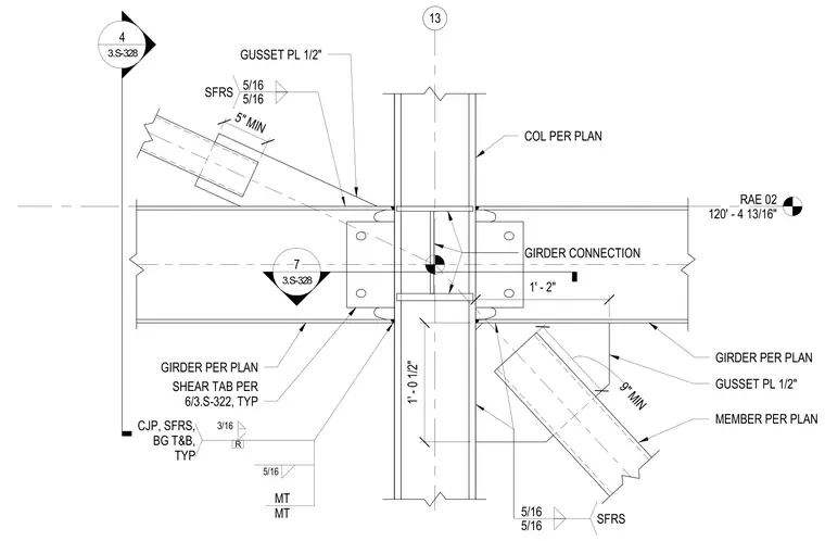
Steel girders connect to a vertical steel column sized per plan using single-plate shear tabs typical on both sides, welded with three-sixteenths inch fillet welds. Diagonal brace members sized per plan intersect the column and girders through half-inch thick gusset plates welded with five-sixteenths inch fillet welds. Special seismic force resisting system requirements apply, including complete-joint-penetration welds and beam web/flange cuts where noted. Additional five-inch and nine-inch minimum clearances are maintained for gusset plate and brace alignments.
RAE 02 120' - 4 13/16" 13 1' - 2" 1' - 0 1/2" 7 3.S-328 4 3.S-328 GUSSET PL 1/2" MEMBER PER PLAN GUSSET PL 1/2" R CJP, SFRS, BG T&B, TYP GIRDER PER PLAN GIRDER PER PLAN 5/16 5/16 SFRS MT MT 5/16 5/16 SFRS COL PER PLAN 3/16 SHEAR TAB PER 6/3.S-322, TYP 5/16 9" MIN GIRDER CONNECTION 5" MIN
Members view this detail in full resolution, download the CAD files (SVG, PDF), and can adapt it in the built-in CAD editor — export DXF, DWG, or PDF.
Start membership