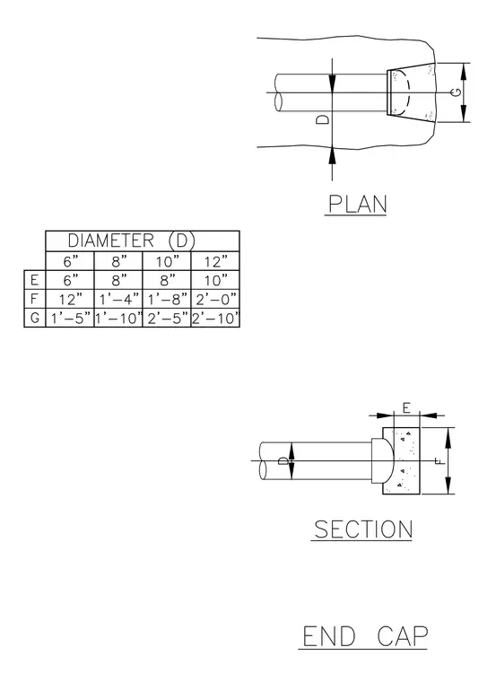
The drawing details a pipe end cap assembly shown in both plan and section views with associated dimensional parameters. A accompanying diameter schedule provides corresponding values for variables E, F, and G based on pipe diameters D of six inches, eight inches, ten inches, and twelve inches. Dimension D designates the pipe diameter, while variables E, F, and G define the spatial clearances and end cap sizing.
Members view this detail in full resolution, download the CAD files (SVG, PDF), and can adapt it in the built-in CAD editor — export DXF, DWG, or PDF.
Start membership