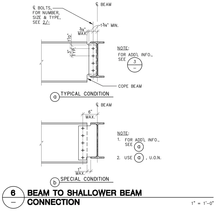
A supported steel beam frames into the web of a shallower supporting beam with a coped top flange. The beam web features a vertical line of bolts spaced typically at three inches on center, positioned between three quarters of an inch maximum and one and three quarters of an inch minimum from the centerlines. The top flange of the incoming beam is coped to clear the supporting flange, maintaining specific clearance limits. A typical condition shows a snug fit at the web connection, while a special condition allows up to six inches maximum offset from the beam centerline with a one-inch maximum gap.
Members view this detail in full resolution, download the CAD files (SVG, PDF), and can adapt it in the built-in CAD editor — export DXF, DWG, or PDF.
Start membership