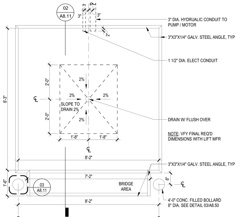
This plan layout outlines a concrete scissor lift pit featuring a central drain with a flush cover and a two percent slope across the slab. Perimeter edges are reinforced with typical three-inch by three-inch by one-quarter-inch galvanized steel angles. Routing provisions include a three-inch diameter hydraulic conduit leading to the pump and motor along with a one-and-one-half-inch diameter electrical conduit. The bridge area approach incorporates four-foot-zero-inch concrete-filled bollards of eight-inch diameter detailed separately. Final required dimensions are specified for verification with the lift manufacturer.
BRIDGE AREA 4'-0" CONC. FILLED BOLLARD 8'' DIA. SEE DETAIL 03/A8.50 NOTE: VFY FINAL REQ'D DIMENSIONS WITH LIFT MFR 3"X3"X1/4" GALV. STEEL ANGLE, TYP 3" DIA. HYDRUALIC CONDUIT TO PUMP / MOTOR 2% SLOPE TO DRAIN 2% 2% 2% 2% 8'-2" 7'-2" 8'-3" 1'-6" 8'-2" 3" 3" 2" 2'-0" 2'-0" 1'-8" 1'-8" 8" DRAIN W/ FLUSH OVER 1 1/2" DIA. ELECT CONDUIT A8.11 03 02 A8.11 3"X3"X1/4" GALV. STEEL ANGLE, TYP
Members view this detail in full resolution, download the CAD files (SVG, PDF), and can adapt it in the built-in CAD editor — export DXF, DWG, or PDF.
Start membership