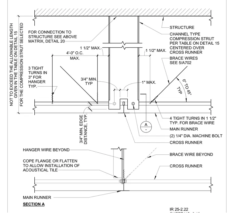
A channel-type compression strut bracing assembly for a suspended acoustical tile ceiling system features a channel compression strut spanning between the overhead structure and the ceiling grid, centered over a cross runner and main runner, with length limited by the table on detail 15. Brace wires installed at an angle between zero and forty-five degrees provide lateral stability, secured with four tight turns in one and a half inches. Vertical support is provided by hanger wires featuring three tight turns in three inches. The cross runner connects to the main runner using two quarter-inch diameter machine bolts with a three-quarter-inch minimum edge distance. Flanges are coped or flattened where necessary to allow the installation of acoustical tiles.
TYP 3/4" MIN. 1" MAX. MAX. 4'-0" O.C. 1 1/2" MAX. 1 1/2" MAX. FOR THE COMPRESSION STRUT SELECTED NOT TO EXCEED THE ALLOWABLE LENGTH GIVEN IN THE TABLE ON DETAIL 15 TYP 0° TO 45° 4 TIGHT TURNS IN 1 1/2" TYP. FOR BRACE WIRE MAIN RUNNER DISTANCE, TYP. 3/4" MIN. EDGE (2) 1/4" DIA. MACHINE BOLT CROSS RUNNER 3 TIGHT TURNS IN 3" FOR HANGER TYP. FOR CONNECTION TO STRUCTURE SEE ABOVE MATRIX, DETAIL 20 STRUCTURE CHANNEL TYPE COMPRESSION STRUT PER TABLE ON DETAIL 15 CENTERED OVER CROSS RUNNER BRACE WIRES SEE 5/A702 COPE FLANGE OR FLATTEN TO ALLOW INSTALLATION OF ACOUSTICAL TILE BRACE WIRE BEYOND CROSS RUNNER HANGER WIRE BEYOND MAIN RUNNER A - SECTION A IR 25-2.22
Members view this detail in full resolution, download the CAD files (SVG, PDF), and can adapt it in the built-in CAD editor — export DXF, DWG, or PDF.
Start membership