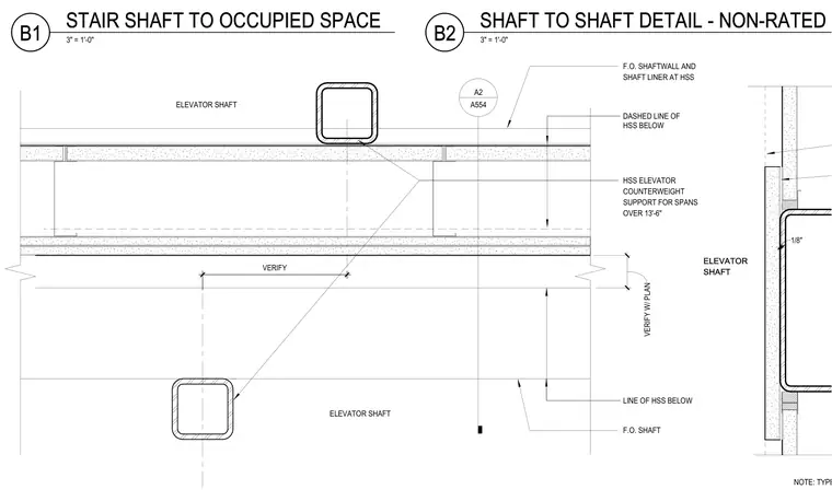
This plan detail shows the interface between elevator shaft walls and structural steel hollow structural sections, including counterweight supports designed for spans over thirteen feet and six inches. Face of shaftwall and shaft liner assemblies align with the hollow structural section framing, with dashed lines indicating framing members located below. Dimensions and alignments are verified with the architectural floor plan. A one-eighth inch joint separates adjacent partitions at back-to-back elevator shafts.
HSS ELEVATOR COUNTERWEIGHT SUPPORT FOR SPANS OVER 13'-6" F.O. SHAFT ELEVATOR SHAFT ELEVATOR SHAFT F.O. SHAFTWALL AND SHAFT LINER AT HSS V E R I F Y DASHED LINE OF HSS BELOW A2 A554 V E R I F Y W / P L A N LINE OF HSS BELOW ELEVATOR SHAFT NOTE: TYPE X PARTITION AT BACK-TO-BACK ELEVATORS 1 / 8 " 3" = 1'-0" B1 STAIR SHAFT TO OCCUPIED SPACE 3" = 1'-0" B2 SHAFT TO SHAFT DETAIL - NON-RATED
Members view this detail in full resolution, download the CAD files (SVG, PDF), and can adapt it in the built-in CAD editor — export DXF, DWG, or PDF.
Start membership