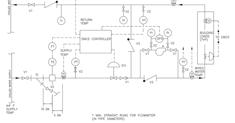
This diagram details a chilled water supply and return piping schematic integrated with an Energy Management and Control System controller. The chilled water supply line enters through isolation valves, strainers, and a flow element with associated flow transmitter requiring specific upstream and downstream straight pipe runs of ten and five pipe diameters. A circulation pump with differential pressure switch and isolation valves manages flow toward the building loads, while pressure transducers, temperature transmitters, and thermowells monitor system performance. Return piping incorporates control valves, pressure and temperature indicators, and check valves before routing back to the chilled water source.
Members view this detail in full resolution, download the CAD files (SVG, PDF), and can adapt it in the built-in CAD editor — export DXF, DWG, or PDF.
Start membership