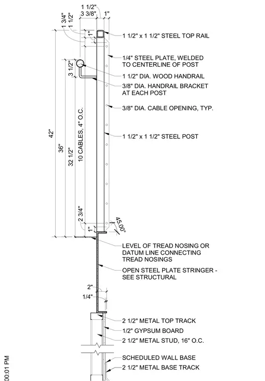
A cable railing assembly is anchored to an open steel plate stringer that transitions to a metal stud partition below. The railing consists of a one-and-a-half-inch square steel top rail and one-and-a-half-inch square steel posts, with a one-quarter-inch steel plate welded to the centerline of the post. Ten individual cables are spaced at four inches on center through three-eighths-inch diameter openings in the post. A one-and-a-half-inch diameter wood handrail is supported by a three-eighths-inch diameter handrail bracket attached at each post. The base of the steel post connects to the stair stringer at a forty-five-degree angle relative to the datum line connecting the tread nosings. The open steel plate stringer bears onto a two-and-a-half-inch metal top track over two-and-a-half-inch metal studs spaced at sixteen inches on center, finished with half-inch gypsum board and a scheduled wall base over a two-and-a-half-inch metal base track.
42" 36" 32 1/2" 3 1/2" 1 1/2" 1" 2 3/4" 10 CABLES, 4" O.C. 1 3/4" 1 1/2" 1 1/2" DIA. WOOD HANDRAIL 3/8" DIA. HANDRAIL BRACKET AT EACH POST 1 1/2" x 1 1/2" STEEL TOP RAIL 1/4" STEEL PLATE, WELDED TO CENTERLINE OF POST 3/8" DIA. CABLE OPENING, TYP. LEVEL OF TREAD NOSING OR DATUM LINE CONNECTING TREAD NOSINGS 45.00° 1 1/2" x 1 1/2" STEEL POST OPEN STEEL PLATE STRINGER - SEE STRUCTURAL 2" 1/4" 2 1/2" METAL TOP TRACK 1/2" GYPSUM BOARD 2 1/2" METAL STUD, 16" O.C. SCHEDULED WALL BASE 2 1/2" METAL STUD 2 1/2" METAL BASE TRACK 1" 1" 3 3/8"
Members view this detail in full resolution, download the CAD files (SVG, PDF), and can adapt it in the built-in CAD editor — export DXF, DWG, or PDF.
Start membership