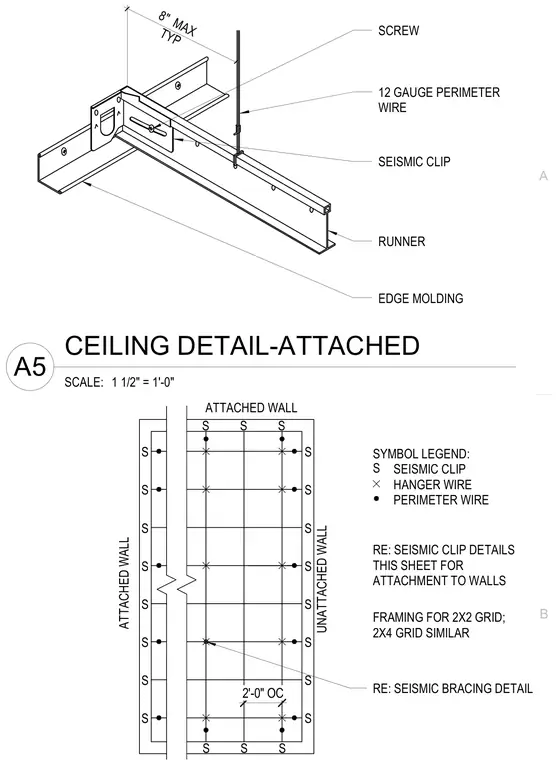
Suspended ceiling grid edge molding connects to the perimeter wall using a runner fastened with a screw, while a 12-gauge perimeter wire supports the seismic clip and runner assembly. The seismic clip secures the runner at a maximum spacing of eight inches typical from the wall support. Plan layout indicates attached and unattached walls with seismic clips, hanger wires, and perimeter wires spaced at two feet on center.
12 GAUGE PERIMETER WIRE SEISMIC CLIP RUNNER EDGE MOLDING SCREW 8" MAX TYP SYMBOL LEGEND: SEISMIC CLIP HANGER WIRE PERIMETER WIRE UNATTACHED WALL RE: SEISMIC BRACING DETAIL RE: SEISMIC CLIP DETAILS THIS SHEET FOR ATTACHMENT TO WALLS ATTACHED WALL S S 2'-0" OC S S S S S S S S S S S S S S S S S S S S S ATTACHED WALL FRAMING FOR 2X2 GRID; 2X4 GRID SIMILAR B A SCALE: 1 1/2" = 1'-0" A5 CEILING DETAIL-ATTACHED
Members view this detail in full resolution, download the CAD files (SVG, PDF), and can adapt it in the built-in CAD editor — export DXF, DWG, or PDF.
Start membership