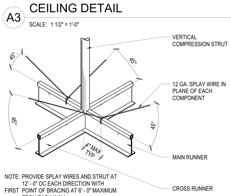
A vertical compression strut connects to the intersection of main and cross runners in a suspended ceiling grid. Twelve-gauge splay wires extend in the plane of each component at forty-five-degree angles to provide lateral seismic resistance. Splay wires and compression struts are spaced at twelve feet on center in each direction with the first point of bracing located a maximum of six feet away. A typical four-inch maximum clearance dimension is maintained at structural interfaces.
45° 45° 45°. 45°. VERTICAL COMPRESSION STRUT 12 GA. SPLAY WIRE IN PLANE OF EACH COMPONENT MAIN RUNNER CROSS RUNNER NOTE: PROVIDE SPLAY WIRES AND STRUT AT 12' - 0" OC EACH DIRECTION WITH FIRST POINT OF BRACING AT 6' - 0" MAXIMUM 4" MAX TYP SCALE: 1 1/2" = 1'-0" A3 CEILING DETAIL
Members view this detail in full resolution, download the CAD files (SVG, PDF), and can adapt it in the built-in CAD editor — export DXF, DWG, or PDF.
Start membership