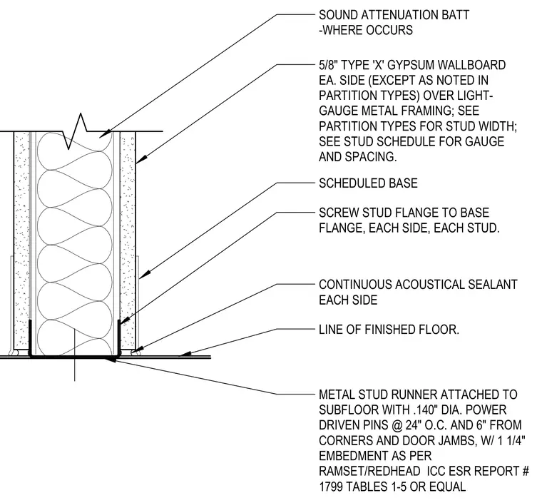
A light-gauge metal stud runner is attached to the subfloor using 0.140-inch diameter power-driven pins spaced at twenty-four inches on center with one and one-quarter inch embedment, placed six inches from corners and door jambs. Light-gauge metal studs are screw-attached through their flanges to the track flange on each side. Five-eighths inch Type X gypsum wallboard is applied to each side over the framing, with sound attenuation batt insulation installed in the wall cavity where required. Continuous acoustical sealant is applied along the base on each side at the line of finished floor, and a scheduled base is installed over the lower gypsum board.
SOUND ATTENUATION BATT -WHERE OCCURS 5/8" TYPE 'X' GYPSUM WALLBOARD EA. SIDE (EXCEPT AS NOTED IN PARTITION TYPES) OVER LIGHT- GAUGE METAL FRAMING; SEE PARTITION TYPES FOR STUD WIDTH; SEE STUD SCHEDULE FOR GAUGE AND SPACING. SCHEDULED BASE SCREW STUD FLANGE TO BASE FLANGE, EACH SIDE, EACH STUD. CONTINUOUS ACOUSTICAL SEALANT EACH SIDE LINE OF FINISHED FLOOR. METAL STUD RUNNER ATTACHED TO SUBFLOOR WITH .140" DIA. POWER DRIVEN PINS @ 24" O.C. AND 6" FROM CORNERS AND DOOR JAMBS, W/ 1 1/4" EMBEDMENT AS PER RAMSET/REDHEAD ICC ESR REPORT # 1799 TABLES 1-5 OR EQUAL
Members view this detail in full resolution, download the CAD files (SVG, PDF), and can adapt it in the built-in CAD editor — export DXF, DWG, or PDF.
Start membership