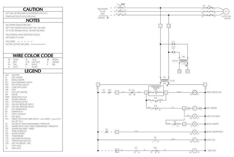
This electrical schematic details the control wiring and power distribution for a supply fan motor operating at 460 volts across three phases. Main power feeds through a main disconnect switch labeled DS1 to supply the motor and a control transformer stepping down voltage to 24V and 115V. Control circuits incorporate a freeze protection timer, a sensor discharge freeze switch, and motor overload protection linked to relays and dampers. Wire color codes, legends, and general notes on copper conductors and terminal ratings are provided alongside the schematic.
Members view this detail in full resolution, download the CAD files (SVG, PDF), and can adapt it in the built-in CAD editor — export DXF, DWG, or PDF.
Start membership