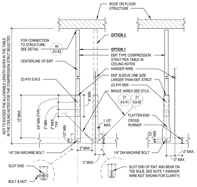
An electrical metallic tubing type compression strut extends downward from the overhead roof or floor structure to the ceiling suspension grid, secured with a slotted end bearing on the tee bulb or connected with a machine bolt and sleeve. Two number ten sheet metal screws fasten the sleeve and strut assembly, complemented by hanger wires and brace wires tied back to the structure. Spacing and dimensional limits govern the maximum allowable lengths and clearances for the compression strut installation.
ROOF OR FLOOR STRUCTURE OPTION 3 OPTION 1 EMT TYPE COMPRESSION STRUT PER TABLE IN CEILING NOTES HANGER WIRE (2) #10 SMS BRACE WIRES SEE DTLS.: FLATTEN END MIN. 1/2". 1/4" DIA MACHINE BOLT 2" MAX 2" MAX. SLOT END OF EMT AND BEAR ON TEE BULB, SEE NOTE 1 (HANGER WIRE NOT SHOWN FOR CLARITY) CENTERLINE OF EMT 6" MIN FOR CONNECTION TO STRUCTURE SEE DETAIL (2) #10 S.M.S. 12" MAX TYP 2" MAX 2" MIN 3/4" MIN (TYP) 1/2" MIN EMT SLEEVE ONE SIZE LARGER THAN EMT STRUT SLOT END BOLT & NUT 1/4" DIA MACHINE BOLT IN THE CEILING NOTES FOR THE COMPRESSION STRUT SELECTED NOT TO EXCEED THE ALLOWABLE LENGTH GIVEN IN THE TABLE 2" MAX 45 A3.42 21 A3.41 21 A3.42 CROSS RUNNER 2" MAX. MAX. 1 1/2".
Members view this detail in full resolution, download the CAD files (SVG, PDF), and can adapt it in the built-in CAD editor — export DXF, DWG, or PDF.
Start membership