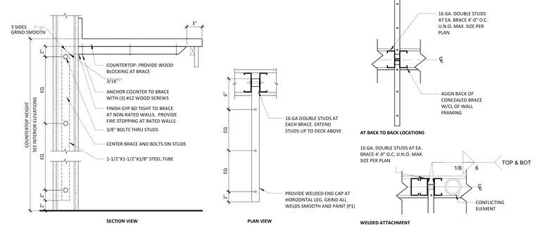
A concealed countertop steel brace is constructed from a one-and-a-half by one-and-a-half by one-eighth inch steel tube anchored within sixteen-gauge double metal studs. The wall framing features studs spaced at four feet on center maximum and extended up to the deck above. The steel tube brace is centered and secured through the studs using three-eighth-inch bolts, while the countertop is fastened to the brace with three number twelve wood screws and supported by internal wood blocking. At the horizontal leg, a welded end cap is provided with welds ground smooth and finished with a specified paint coating. Gypsum board finishes tight to the brace at non-rated walls, with fire stopping added at rated walls.
PLAN VIEW SECTION VIEW 16 GA DOUBLE STUDS AT EACH BRACE. EXTEND STUDS UP TO DECK ABOVE 3/8" BOLTS THRU STUDS ANCHOR COUNTER TO BRACE WITH (3) #12 WOOD SCREWS COUNTERTOP: PROVIDE WOOD BLOCKING AT BRACE CENTER BRACE AND BOLTS ON STUDS PROVIDE WELDED END CAP AT HORIZONTAL LEG. GRIND ALL WELDS SMOOTH AND PAINT (P1) FINISH GYP BD TIGHT TO BRACE AT NON-RATED WALLS. PROVIDE FIRE STOPPING AT RATED WALLS 1-1/2"X1-1/2"X1/8" STEEL TUBE 2" 2" EQ EQ 3" 6" 2" EQ EQ 2" SEE INTERIOR ELEVATIONS COUNTERTOP HEIGHT 3 SIDES GRIND SMOOTH 3/16" 16 GA. DOUBLE STUDS AT EA. BRACE 4'-0" O.C. U.N.O. MAX. SIZE PER PLAN ALIGN BACK OF CONCEALED BRACE W/CL OF WALL FRAMING C L AT BACK TO BACK LOCATIONS CONFLICTING ELEMENT WELDED ATTACHMENT C L 1/8 6 TOP & BOT 16 GA. DOUBLE STUDS AT EA. BRACE 4'-0" O.C. U.N.O. MAX. SIZE PER PLAN
Members view this detail in full resolution, download the CAD files (SVG, PDF), and can adapt it in the built-in CAD editor — export DXF, DWG, or PDF.
Start membership